
Valves in US data center liquid cooling: which valve goes where
A liquid cooling loop needs as many valves as it has branches. This guide sets out which valve goes where, what it should be made of, and which flanges each one bolts to.
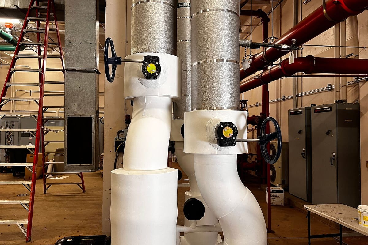
A data center liquid cooling loop uses butterfly valves to isolate CDUs, headers and rows, full-bore ball valves at every rack branch and for drains and vents, static balancing valves to set the flow, dual plate check valves at pumps and Y-strainers ahead of pumps and heat exchangers, all in 304L or 316L stainless on the technology cooling side. Every flanged, lug or wafer valve sits between two flanges of the line's class, and those flanges are what we make.
Which valve goes where
| Location | Valve | Usual size and ends |
|---|---|---|
| CDU primary and secondary connections | Butterfly valve, lug type | NPS 2.5 to 6; lug between Class 150 or PN 16 flanges, or tri-clamp at a sanitary CDU connection |
| CDU headers and row manifolds | Butterfly valve, lug or wafer | NPS 4 to 12; flanged |
| Rack branches, supply and return | Ball valve, full bore | NPS 1 to 2; flanged, tri-clamp or threaded |
| Drains, vents, instrument and sample points | Ball valve | 1/4 in to NPS 1; threaded or weld end |
| Row and rack branches | Static balancing valve | To suit the branch; flanged or threaded |
| Pump discharge, make-up lines | Dual plate check valve (NRV) | Wafer, between flanges |
| Ahead of pumps, plate heat exchangers and CDU skids | Y-strainer | Flanged; Vertiv calls for a 500 µm strainer on the primary side of its larger CDUs |
| Riser tops and manifold high points | Air vent valve | Threaded; never above IT equipment |
How many of each a pod needs is counted in our CDU to rack piping guide: about fifty valves for twenty racks, most of them the rack branch ball valves.
Isolation: butterfly and ball valves
Every CDU, header and row needs isolation so a part of the loop can be drained without stopping the rest, and Vertiv recommends supply and return isolation at every rack position. Butterfly valves do the job on the large lines, in lug or wafer patterns. Full-bore ball valves take the rack branches, where a full bore keeps the pressure drop of each branch down, and the small drain, vent and instrument points. Where a CDU or manifold has sanitary connections, the joint is a tri-clamp fitting instead of a flange.
Butterfly valves
Lug or wafer at CDUs, headers and rows, and the flanges they bolt between.
Ball valves
Full bore at every rack branch, plus drains, vents and instruments.
Tri-clamp fittings
Ferrule, gasket and clamp: where sanitary joints meet flanged headers.
Balancing, check valves and strainers
- Static balancing valves set the flow to each row or rack branch, so racks near the CDU do not take more than their share. Balance is then proved rack by rack in commissioning, as our secondary fluid network guide explains.
- Dual plate check valves stop backflow at pump discharges and on make-up lines in chilled water and coolant circuits. Their wafer body fits between two flanges of the line's class.
- Y-strainers protect pumps, plate heat exchangers and CDU skids. Vertiv's 1,350 and 2,300 kW CoolChip CDUs need a field-supplied 500 µm strainer on the primary side; the secondary side has its own 25 or 50 µm filters.
- Air vent valves release air at riser tops and manifold high points. Vertiv's TCS guidance is clear on one rule: never put automatic air vents above IT equipment.
Materials and tests to specify
| Part | Technology cooling loop | Chilled and condenser water |
|---|---|---|
| Body and wetted metal | SS 316L or 304L | SS 304L or 316L where the facility water is stainless |
| Seats and seals | EPDM (peroxide-cured, per Vertiv) or as the coolant supplier approves | EPDM for water and glycol |
| Ends | Flanged, lug, tri-clamp or weld end | Flanged, lug or wafer |
| Tests to ask for | Hydrostatic, pneumatic and functional test; PMI; material traceability | Hydrostatic and functional test |
Gaskets are wetted parts too: check the elastomer against the coolant supplier's approved list, as our gasket guide explains. On the technology cooling loop, keep carbon steel and cast iron bodies out: their corrosion products are what the loop's filters and cold plates must not see.
The flanges every valve needs
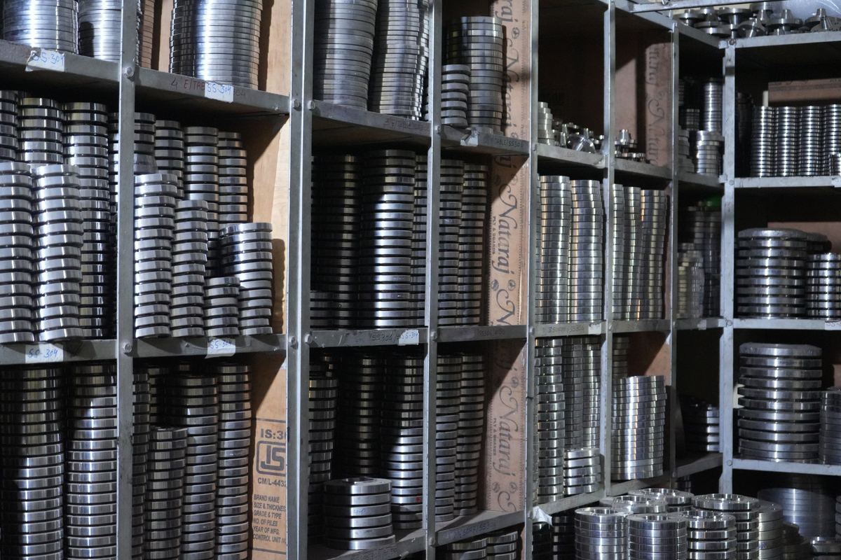
Lug and wafer butterfly valves, and flanged ball valves, check valves and strainers, each sit between two flanges of the line's class: ASME B16.5 Class 150 or EN 1092-1 PN 16 on most cooling loops. Weld neck flanges bored to the pipe schedule are the usual pairing, because their bore matches the pipe and clears a butterfly disc; a lap joint flange turns to line up with a valve's bolt holes. We make these flanges in 316L, 304L and carbon steel, and supply the butt weld fittings and pipe in the same grades, each line on an EN 10204 3.1 certificate. Send the valve schedule with your enquiry and the flange count follows from it.
Valves on US projects
US specifications put HVAC and cooling water valves under CSI MasterFormat Section 23 05 23, General-Duty Valves for HVAC Piping, and name a valve standard for each type: typically MSS SP-67 or API 609 for butterfly valves, MSS SP-110 for ball valves and API 594 for wafer and dual plate check valves. Federal projects follow UFGS 23 64 26 for chilled and condenser water. The valve standard governs the valve; the flanges it bolts to are ASME B16.5 Class 150 on most US cooling loops.
| Valve | Standard named in US specifications | Where it sits |
|---|---|---|
| Butterfly, lug or wafer | MSS SP-67 or API 609 | CDUs, headers, rows, mains: NPS 2-1/2 and up |
| Ball, full bore | MSS SP-110 (threaded and socket-weld ends); flanged ends drilled to ASME B16.5 Class 150 | Rack branches, drains, vents: NPS 2 and below |
| Dual plate check (wafer) | API 594 | Pump discharges, make-up lines |
| Strainer, Y-type | Project specification; flanged ends to ASME B16.5 Class 150 | Ahead of pumps, heat exchangers, CDU skids |
On the technology cooling side, US projects follow the same rules as everywhere else: stainless bodies, elastomers from the coolant supplier's list, no thread tape or pipe dope in the loop. The flanges for these valves ship from our works in India in NPS sizes, with ASTM grades on the material test reports; a Class 150 flange in F316L is rated 230 psi at 100 °F, well above the 60 psi OCP gives for liquid-to-chip loops. How documents and shipping work for a US site is set out in ordering flanges from India.
Frequently asked questions
Do you make or supply valves?
No. We make flanges, and supply butt weld fittings and pipe in the same grades. This guide explains which valves a cooling loop needs and how each one meets its flanges, so the flange schedule you send us fits the valves you buy.
Which valve goes where in a liquid cooling loop?
Butterfly valves isolate CDUs, headers and rows; full-bore ball valves isolate each rack branch and serve drains, vents and instruments; static balancing valves set the flow to rows and racks; dual plate check valves stop backflow at pumps; Y-strainers protect pumps, heat exchangers and CDU skids.
What material should valves on the technology cooling loop be?
Stainless steel in the same family as the pipe, 304L or 316L, with elastomers approved by the coolant supplier. Vertiv recommends peroxide-cured EPDM for elastomers in single-phase TCS loops. Keep carbon steel and cast iron bodies off the TCS.
Which end connections do cooling loop valves use?
Lug and wafer butterfly valves fit between ASME B16.5 Class 150 or EN 1092-1 PN 16 flanges; flanged ball valves, check valves and strainers carry flanges drilled to the same standard; tri-clamp ends suit CDU and manifold connections; threaded or weld ends suit small bore. Whatever the valve, the mating flanges need the same drilling and a bore that clears its moving parts.
How many flanges do the valves need?
Two for every flanged, lug or wafer valve, of the line's class and facing. Count them from the valve schedule, as our CDU to rack piping guide does for a pod of twenty racks, where the flanges at the valves are most of the flange order.
Sources
- Vertiv, Guidelines for Deployment of Single Phase Technology Cooling System, SL-80056 Rev A, February 2025 (elastomers, air vents)
- Vertiv, Designing liquid cooling infrastructure for scalability: best practices for future growth, 11 May 2026 (isolation at every rack position)
- Vertiv, CoolChip CDU 600, 1350 and 2300 kW data sheet, SL-80005, May 2026 (connections, primary strainer, secondary filters)
- Open Compute Project, Modular Technology Cooling System for "Cloud Scale", version 1.0, 25 August 2025 (joint types)
- CSI MasterFormat Section 23 05 23, General-Duty Valves for HVAC Piping; MSS SP-67, MSS SP-110, API 594 and API 609 (valve standards named in US specifications)