
CDU to rack piping for US AI data centers, with a sample BOQ
Between the CDU and the server racks sits a short run of stainless piping with a lot of parts in it. This guide follows the coolant from CDU to rack, sizes each level for 142 kW racks, and counts the flanges, valves and fittings in a sample bill of quantities.
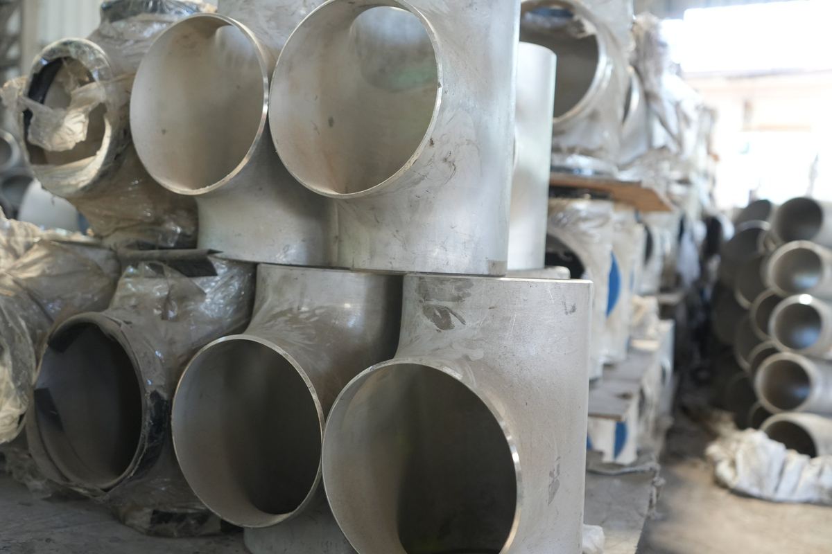
From the CDU to the racks, coolant passes through five levels of piping: the CDU connection, the CDU header, the row manifolds, a branch to every rack and the in-rack manifold with its hoses. Flanges and fittings sit at every valve, module break, header end and branch. For racks of about 142 kW, size the branches at NPS 2 (DN 50), the row manifolds at NPS 6 (DN 150) and the header at NPS 8 (DN 200) in Sch 10S stainless. Our sample pod of twenty racks and four CDUs needs about 130 flanges, 110 elbows, 50 tees and 50 valves, listed below.
The levels from CDU to rack
| Level | What it does | Joints and parts |
|---|---|---|
| CDU connection | Takes coolant out of the CDU and back in; many CDUs have sanitary (tri-clamp) connections | Sanitary ferrule spool or flange, isolation valve, elbows |
| CDU header | Joins the CDUs so they share the load and cover for each other (N+1) | Butt welded pipe, reducing tees for each CDU and row, blind flanges at the ends |
| Row manifold | Runs along a row of racks, overhead or under the floor | Butt welded pipe, a reducing tee per rack, row isolation valve, flanged module breaks, blind end |
| Rack branch | Drops from the manifold to one rack, supply and return | Isolation valve with two flanges, elbows, connection for the rack hose |
| In-rack manifold and hoses | Feeds each server through dripless quick disconnects | Supplied with the rack |
How to lay out, balance and commission the whole network is in our secondary fluid network design guide; this guide is about what goes into the bill of quantities.
The example pod
The example uses public figures only: racks of the NVIDIA GB300 NVL72 class at 142 kW, the figure in Vertiv's reference design; 0.4 gpm (1.5 L/min) per kW, the Open Compute Project's rule of thumb; and Vertiv's 1,350 kW CoolChip CDU, which has 4 in sanitary connections. Twenty racks in two rows of ten make 2.84 MW. Three CDUs carry it at 70% of their rating, the 60 to 70% that Vertiv suggests as a starting point, and a fourth gives N+1.
| Level | Flow | Pipe | Velocity |
|---|---|---|---|
| Rack branch, one rack | 56 gpm (213 L/min) | NPS 2 (DN 50), bore 54.8 mm | 4.9 ft/s (1.51 m/s) |
| Row manifold, ten racks | 563 gpm (2,130 L/min) | NPS 6 (DN 150), bore 161.5 mm | 5.7 ft/s (1.73 m/s) |
| CDU header, twenty racks | 1,125 gpm (4,260 L/min) | NPS 8 (DN 200), bore 211.6 mm | 6.6 ft/s (2.02 m/s) |
| CDU branch, four CDUs sharing | 281 gpm (1,065 L/min) each | NPS 4 (DN 100), bore 108.2 mm | 6.3 ft/s (1.93 m/s) |
| CDU branch, one CDU stopped | 375 gpm (1,420 L/min) each | NPS 4 (DN 100) | 8.4 ft/s (2.57 m/s); keep these runs short |
The branch size matches OCP's rating of 170 to 220 kW for an NPS 2 branch. Not all of a rack's heat goes to the liquid, so these flows carry a margin; check them against the rack maker's figures and the CDU's selection. If a third row is likely, an NPS 10 header (1.29 m/s, 4.2 ft/s) saves replacing it later.
Sample BOQ: flanges, fittings and valves
For the pod above, with ASME B16.5 Class 150 flanges, Sch 10S pipe and 316L throughout. Pipe is measured from the layout and is not listed.
| Item | Size | Material | Qty | Where |
|---|---|---|---|---|
| CDU connections | Four CDUs, supply and return | |||
| Sanitary ferrule with clamp and gasket | 4 in | 316L | 8 | CDU secondary connections (4 in sanitary on a 1,350 kW CoolChip CDU) |
| Butterfly valve, lug type, Class 150 | NPS 4 (DN 100) | 316 disc, EPDM seat | 8 | Isolates each CDU from the header |
| Weld neck flange, Class 150 RF, bored Sch 10S | NPS 4 (DN 100) | ASTM A182 F316L | 16 | Both sides of each CDU valve |
| 90° long radius elbow, Sch 10S | NPS 4 (DN 100) | ASTM A403 WP316L | 16 | CDU branches |
| Reducing tee, Sch 10S | NPS 8 × 4 | ASTM A403 WP316L | 8 | CDU branches on the header |
| CDU header | Supply and return | |||
| Weld neck flange, Class 150 RF, bored Sch 10S | NPS 8 (DN 200) | ASTM A182 F316L | 6 | One module break per line, and the blind ends |
| Blind flange, Class 150 RF | NPS 8 (DN 200) | ASTM A182 F316L | 2 | Header ends, left for a fifth CDU |
| Reducing tee, Sch 10S | NPS 8 × 6 | ASTM A403 WP316L | 4 | Take-offs to the two rows |
| 90° long radius elbow, Sch 10S | NPS 8 (DN 200) | ASTM A403 WP316L | 4 | Header routing |
| Row manifolds | Two rows, supply and return | |||
| Butterfly valve, lug type, Class 150 | NPS 6 (DN 150) | 316 disc, EPDM seat | 4 | Isolates each row manifold |
| Weld neck flange, Class 150 RF, bored Sch 10S | NPS 6 (DN 150) | ASTM A182 F316L | 20 | Row valves, one module break per manifold, blind ends |
| Blind flange, Class 150 RF | NPS 6 (DN 150) | ASTM A182 F316L | 4 | Manifold ends, left for more racks |
| Reducing tee, Sch 10S | NPS 6 × 2 | ASTM A403 WP316L | 40 | One per rack connection |
| 90° long radius elbow, Sch 10S | NPS 6 (DN 150) | ASTM A403 WP316L | 8 | Manifold routing |
| Rack branches | Twenty racks, supply and return | |||
| Ball valve, flanged, Class 150 | NPS 2 (DN 50) | 316 | 40 | Isolation at every rack position |
| Weld neck flange, Class 150 RF, bored Sch 10S | NPS 2 (DN 50) | ASTM A182 F316L | 80 | Both sides of each branch valve |
| 90° long radius elbow, Sch 10S | NPS 2 (DN 50) | ASTM A403 WP316L | 80 | Drops from the manifold to the rack |
| Sanitary ferrule with clamp and gasket | 2 in | 316L | 40 | Hose connection to the in-rack manifold, or a flange to suit the rack maker |
| Joint sets | One per flanged joint | |||
| Gasket, Class 150 RF, PTFE or peroxide-cured EPDM | NPS 2, 4, 6 and 8 | To suit the coolant | 80, 16, 16 and 4 | Every flanged joint |
| Stud bolt set with nuts, ASME B16.5 Class 150 bolting | NPS 2, 4, 6 and 8 | ASTM A193 B8M with A194 8M, or as specified | 80, 16, 16 and 4 | 4 × 5/8 in at NPS 2, 8 × 5/8 in at NPS 4, 8 × 3/4 in at NPS 6 and 8 |
| Part | Whole pod | Per rack position |
|---|---|---|
| Weld neck flanges | 122 (80 NPS 2, 16 NPS 4, 20 NPS 6, 6 NPS 8) | 4 × NPS 2 |
| Blind flanges | 6 (4 NPS 6, 2 NPS 8) | None |
| Elbows, 90° long radius | 108 | 4 × NPS 2 |
| Reducing tees | 52 | 2 × NPS 6 × 2 |
| Valves | 52 (40 ball, 12 butterfly) | 2 × NPS 2 ball valves |
| Flanged joints (gaskets and stud bolt sets) | 116 | 4 |
| Sanitary ferrules | 48 (8 × 4 in, 40 × 2 in) | 2 × 2 in |
Nearly two thirds of the flanges in the pod are NPS 2 branch flanges: four for every rack, because every rack position gets supply and return isolation. Vertiv recommends that isolation, and it lets one rack be drained and swapped without stopping its row. Blind flanges at the manifold and header ends do the same job for growth: new racks or a fifth CDU tie in without cutting live pipe.
Choosing the parts
- Flanges: weld neck flanges bored to Sch 10S, so the bore runs flush with the pipe; a lap joint flange with stub end where the bolt holes must line up with a valve or CDU. No slip-on flanges in the technology cooling loop: their inside fillet weld leaves a crevice.
- Material: ASTM A182 F316L or F304L, pickled and passivated to ASTM A380 and A967, with 100% PMI and an EN 10204 3.1 certificate. The TCS flange page explains why.
- Fittings: ASTM A403 WP316L butt weld elbows, tees and reducers in the same schedule as the pipe, so the weld joints match.
- Blinds: 316L blind flanges, never carbon steel, at every end left for growth.
- Valves: lug butterfly valves at the CDUs and rows, full-bore ball valves at the rack branches, and tri-clamp fittings where the CDU or rack hose has sanitary connections.
- Gaskets and bolting: PTFE or peroxide-cured EPDM, which Vertiv recommends for the coolant loop, checked against the coolant supplier's list; stainless stud bolts to the ASME B16.5 Class 150 bolting for each size.
- Pressure class: Class 150 (PN 16) is ample for loops that run at a few bar; it is chosen because valves, strainers and CDU adapters are drilled to it.
Every flange size in the list can be drawn and downloaded as a PDF or DXF with our drawing tool, and added to a quote request line by line.
What to send us for a BOQ
- The layout or isometrics, or your own take-off;
- rack count and power per rack, and the CDU model and its connection type;
- pipe material and schedule, and the flange standard and class (ASME B16.5 Class 150 or EN 1092-1 PN 16);
- valve types at the CDUs, rows and racks, and anything to be left for growth;
- passivation, PMI and certificate requirements.
Send it through our quote form. We return a line-by-line quotation for the flanges and fittings, and we can supply the pipe in the same grade as part of the package. The valves in the BOQ are for your valve supplier; our valve guide shows how each one meets its flanges.
The same take-off for a US project
In US units the example runs at 0.4 gpm per kW: 56 gpm per rack, 563 gpm per row and about 1,125 gpm for the pod. NPS 2 branches run at 4.9 ft/s, the NPS 6 row manifolds at 5.7 ft/s and the NPS 8 header at 6.6 ft/s; NPS 10 brings the header down to 4.2 ft/s if a third row is likely. A US mechanical contractor prices the take-off from lines like these:
Weld neck flange, NPS 2, ASME B16.5 Class 150 RF, bore Sch 10S, ASTM A182 F316L, 4 pcs. Elbow, 90° LR, NPS 2 Sch 10S, ASTM A403 WP316L, 4 pcs. Tee, reducing, NPS 6 × 2 Sch 10S, ASTM A403 WP316L, 2 pcs. Each with a mill test report tied to the heat number stamped on the part.
On federal work the flange drawings for each size go into the SD-03 product data submittal; our flange drawings guide explains the PDF sheets. Inspection, documents and shipping for a US delivery are set out in ordering flanges from India.
Frequently asked questions
What goes into a BOQ for liquid cooling piping?
Everything between the CDU and the rack hoses: the transition from the CDU connection, isolation valves, the CDU header, row manifolds with a branch tee for every rack, branch valves, flanges, elbows, reducers, blind flanges for future racks, gaskets and stud bolts, plus the pipe measured from the layout. Vents, drains and sensors are added where the layout puts them.
How many flanges does one liquid-cooled rack need?
In our example, four NPS 2 (DN 50) weld neck flanges per rack: two at the supply valve and two at the return valve, with four gaskets and four stud bolt sets. A rack whose branch valves are threaded or tri-clamp needs no flanges at the branch, but OCP discourages threaded joints in the field.
Which flange goes on the CDU connection?
It depends on the CDU. Vertiv's CoolChip CDUs have 2.5, 4 or 6 in sanitary (tri-clamp) connections, so the piping starts with a sanitary ferrule welded to a short spool, then a flanged isolation valve. Where a CDU has flanged nozzles, use a weld neck flange, or a lap joint flange with a stub end if the bolt holes must line up.
Can the flanges, fittings and pipe come from one supplier?
Yes. We supply complete packages of flanges, butt weld fittings and pipe in the same grade, so one set of heat-numbered certificates covers the CDU-to-rack piping. The valves come from your valve supplier; send their data sheets with the enquiry so the flange drilling and bores can be checked against them.
Do you price a BOQ from a layout?
Yes. Send the layout or your own take-off with the rack count, rack power, pipe schedule and valve types through our quote form. We reply with a line-by-line quotation for the flanges and fittings, and every enquiry gets a reply.
Sources
- Vertiv, news release on its reference architecture for the NVIDIA GB300 NVL72, 11 June 2025 (142 kW per rack)
- Vertiv, CoolChip CDU 600, 1350 and 2300 kW data sheet, SL-80005, May 2026 (capacities, 2.5, 4 and 6 in sanitary connections, filtration)
- Vertiv, Designing liquid cooling infrastructure for scalability: best practices for future growth, 11 May 2026 (rack isolation, blanked connections, CDU utilization)
- Vertiv, Guidelines for Deployment of Single Phase Technology Cooling System, SL-80056 Rev A, February 2025 (304L or 316L, peroxide-cured EPDM)
- Open Compute Project, Modular Technology Cooling System for "Cloud Scale", version 1.0, 25 August 2025 (1.5 L/min per kW, branch ratings, joint types)
- ASME B36.19M, Stainless Steel Pipe (Sch 10S bores); ASME B16.5 (Class 150 bolting)
- RIC calculation of flows, velocities and quantities for the example pod